Background
As a bona fide Corvair nut since 1983, I have always wanted a strong-performing street car. My first Corvair was a '62 Monza coupe with an 80 HP engine—not exactly a high-performance machine. As I learned about Corvair engines, I realized that the power of the stock engine could be improved in several ways, but that many of the "improvements" (radical cam, higher compression ratio, etc.) seriously degraded streetability and that others (turbo-charging, center-mount 4-barrel carb, etc.) were expensive to maintain and had some reliability problems.
I checked out V8-powered Corvairs and admired their incredible performance, but was not happy with the necessary trade-offs (loss of interior room with most of the conversions, problems with transaxle strength, etc.). And, more importantly, I thought it was much more of a challenge to improve the stock Corvair engine's performance, and that doing so retained the essence of what it means to drive a Corvair. (There's nothing like the exhaust note of a horizontally-opposed Corvair engine!)
Given these factors, I began exploring other avenues. As many performance enthusiasts have said, "There's no substitute for cubic inches". I learned that a .060" overbored stock cylinder was fairly common. I also learned that .125" overbore kits were available but that the resulting cylinder walls were very thin. I eventually learned about the famous Salih Engineering and Stokes Engineering custom piston and barrel sets, which, at their largest, had a .3125" overbore. That was what I was after!
Trying to find a set of Salih or Stokes barrels was no easy feat—I missed out on a couple of them. They weren't cheap either—at least $1000 for a set of six. Feeling like I was headed down a dead-end street, I talked with my friend Linn Richardson. As luck would have it, he had recently heard about large-displacement piston and barrel sets for air-cooled VW 4-cylinder engines, manufactured by Mahle (a.k.a. Cima).
To make a long story short, Linn ordered a set of the 94 mm pistons and barrels in the summer of 1994, and after some experimentation with master machinist John Barnes of Seattle, determined that building a big-bore Corvair engine based on these components was very feasible. I quickly signed myself up to be the "guinea pig" for the first of these engines Linn and John were to build.
Size comparison
Below is a table, sorted by increasing displacement, that compares various Corvair engine cylinder sizes and the resulting displacements. All of these configurations retain the stock stroke of 2 15/16" (2.9375").
Overbore amount in decimal in. from stock late model |
Bore (cylinder diameter) |
Displacement |
|||
|---|---|---|---|---|---|
fractional in. |
decimal in. |
millimeters |
cubic in. |
liters |
|
None |
3 7/16 |
3.4375 |
87.2998 |
163.66 |
2.68 |
.0600" overbore |
3 1/2 (aprx.) |
3.4975 |
88.8238 |
169.43 |
2.78 |
.1250" overbore (Salih Engineering, among others) |
3 9/16 |
3.5625 |
90.4875 |
175.68 |
2.88 |
.1846" (Cima / Mahle 92 mm; Graham Dell's Ultravan engine) |
3 5/8 (aprx.) |
3.6221 |
92.0000 |
181.61 |
2.98 |
.1875" overbore (Salih Engineering) |
3 5/8 |
3.6250 |
92.0750 |
181.76 |
2.98 |
.2633" (Cima / Mahle 94 mm; CorvairKid's engine & Mighty Mouse) |
3 7/10 (aprx.) |
3.7008 |
94.0000 |
189.75 |
3.11 |
.3125" overbore (Stokes Engineering) |
3 3/4 |
3.7500 |
95.2500 |
194.66 |
3.19 |
In computing the figures in the table above, I relied on several useful formulas.
Graham Dell's 3-liter Ultravan engine was also built by Linn and John and powers Ultravan #292, which Graham is restoring extensively. Graham is going all-out—his engine is fuel injected using custom fuel rails and Haltech's E6A controller (which has been superceded by later models). (Check Haltech's home page for info on their products.)
Components
Below are some "visual aids" to help conceptualize the size difference between stock Corvair late model components and the 3.1 liter (94 mm) package.
(Click on an image to see a larger size picture.)
|
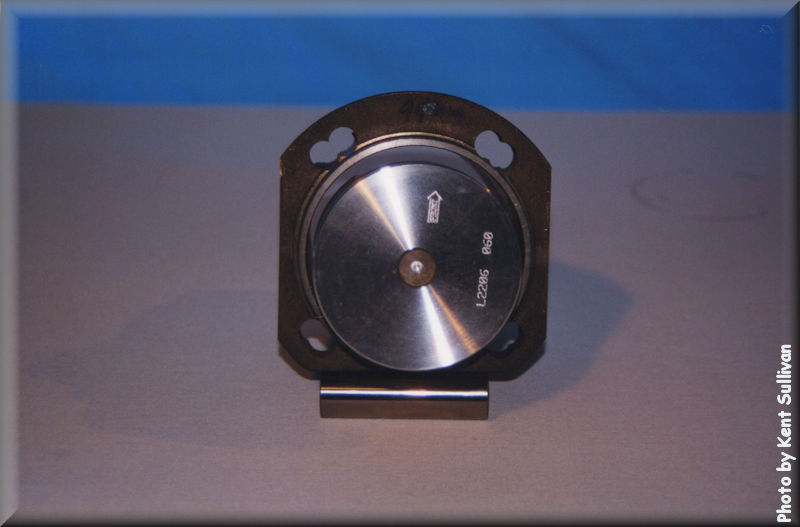
Perhaps the most dramatic demonstration of the size difference is seeing a .060" overbore piston inside of a 94 mm cylinder. |
|
The base of a .060" overbore cylinder sits snugly inside the top of a 94 mm cylinder. |
|
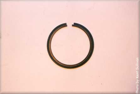
A .030" overbore piston ring fits snugly within a 94 mm piston ring. |

Stage 1 engine details
Since my engine was the first 94 mm job that Linn and John attempted, we decided to be fairly conservative. We made reliability the #1 priority so that we could assess the longevity of the Cima/Mahle components. Exotic fuel intake systems, turbocharging, etc. could come later.
The engine started from literally nothing—Linn selected the best bare case he had on hand and the engine was built from the ground up. Every part was thoroughly inspected, cleaned, painted (if necessary), balanced (if necessary), etc. We didn't use a NOS crank or heads, just used ones with no structural damage. (The heads were painstaking deflashed.)
I didn't take a lot of pictures of the particular engine assembly details but the Mighty Mouse feature captures a process very similar to the one that John and Linn used. (Check out the annotations to see the major differences in our process.)
(Click on an image to see a larger size picture.)
|
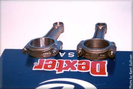
A modified connecting rod on the left shows material removed to clear the piston skirt on the opposite side (compare to unmodified rod on the right side) |
|
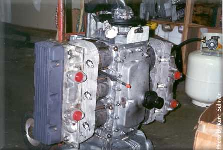
Here is a shot of the Stage 1 engine ready to be installed (March 1995). |
Below is a laundry list of some of the noteworthy engine components:
- Heads configured with 9.25:1 compression ratio
- Otto Parts OT-20 cam (See details on cam specs)
- Roller rockers; HD rocker studs
- Dale Manufacturing flywheel
- Dale Manufacturing harmonic balancer
- Chrysler electronic ignition (as sold by Dale Manufacturing)
- Modified top cover baffle (trimmed and bolted to top cover to eliminate one gasket)
- Clark's Ultimate valve covers and oil pan with extra-deep oil pickup
- Single-wire internally-regulated alternator
- NGK B5HS spark plugs; mag plug wires
- Rochester 4-carb setup, modified by Bob Coffin ("Pro Flow" treatment, slightly larger jets, jets relocated to not starve during hard cornering)
- Clark's exhaust extractors (the larger size)
- Amsoil synthetic oil
- Oil filter adapter for an A/C-equipped car, permitting the use of a longer Amsoil oil filter
Also, check out details about some of the features of the car in which this engine was installed (1995-98).
Note: This engine is now in Dean Richardson's 5-speed Corvair. Dean has made a few changes; notably, a quieter exhaust.
Dyno testing
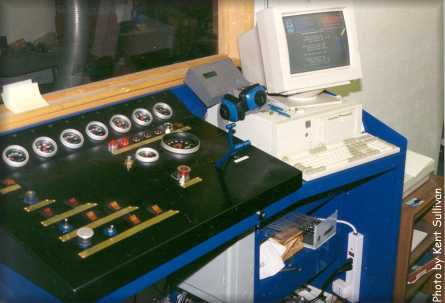
We spent three days in August, 1998 testing the Stage 1 engine at Austin's Pro/Max Performance Center in Puyallup, WA. (They have since moved to nearby Tacoma.) Their engine dyno is an inertia type, meaning that the engine is connected (through a reduction drive) to a spinning mass. The dyno is designed for wide-open throttle "pulls" only, not for tuning an engine by holding it at a given RPM.
Obviously, this required removing the engine from the car. Austin's Pro/Max also has a chassis dyno, which is good for tuning the engine in the car (and for estimating horsepower delivered to the drive wheels).
(Click on an image to see a larger size picture.)
|
The control center for the dyno is impressive, huh? The PC on the right does all of the data collection. The data is saved to disk for later analysis or report printing. The ear protection comes in handy when they're testing a top fuel dragster engine! |
|
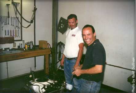
Linn Richardson prepares the engine for testing while Rick Course looks on. Rick is a friend of Linn's and has some experience with the Haltech fuel injection controller, which I'll be using in later stages. |
|
Duane Cartwright, creator of the fuel injection system Clark's Corvair Parts is going to be selling, dropped in for a visit from Portland, OR. We briefly ran his fuel injection manifolds on my engine but had problems tuning the setup since the dyno can't be set to hold at a certain RPM. See the Stage 4 page for some pictures. |
|
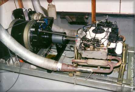
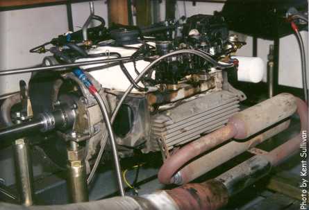
Here's the engine on the dyno stand viewed from the driver's side. To accommodate Austin's exhaust hose setup we had to reverse the exhaust mounting temporarily. You can see that we tested the engine in "as installed" configuration—with fan, belt, alternator, full exhaust, and shrouding. |
|
John Barnes machined an adapter to connect the dyno's "arm" to the Corvair bellhousing. The folks at Pro/Max had never dynoed a Corvair engine before but were happy to help us prepare for the runs. |
|
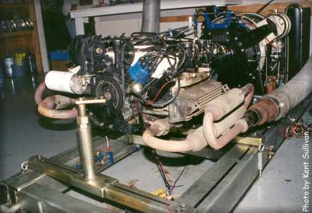
Here's a view from the rear of the engine. The Chrysler ignition box is just barely visible on the floor in the front right of the picture (behind the dyno frame rail). |
|
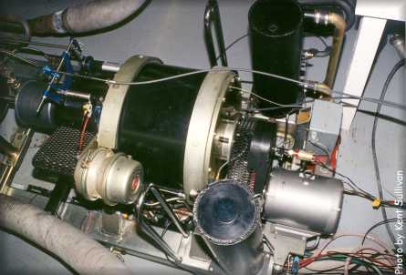
This close-up of the inertia wheel clearly shows that it was built for engines putting out much more horsepower and torque, but it worked just fine for our application. |
Dyno results graph
I made the graph below using data from our best dyno run and data published in Chevrolet's "1965 Corvair 164 Cu. In. HO-6 Stock Engine Test" (available as a reprint from Clark's. Order part C7958.)
The graph is formatted to be as much like the original Chevy graph as possible. Torque, in 2 lb. ft. increments, is shown on the left scale while horsepower, in 1 HP increments, is shown on the right scale. RPM along the X-axis is given in units of 50.
Click on the image below to see the full-sized graph:
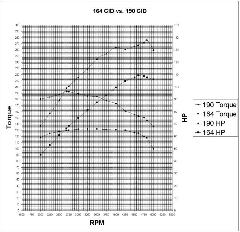
Both sets of results were from "as installed" tests (a.k.a. "SAE net torque and horsepower"). As you can see from the graph, the Stage 1 engine exceeds the stock 140 HP/164 CID engine in both torque (46%) and horsepower (27%)—no surprise given the different cams, carburetors, and exhaust. (The expected improvement due solely to displacement increase is 15%.)
Of interest is that the Stage 1 engine's peak torque is developed much sooner: 193.1 lb. ft. @ 2692 RPM vs. 132.1 lb. ft. @ 3400/3600 RPM. Peak HP is developed at a little higher RPM—138.2 HP @ 4830 RPM vs. 109.4 HP @ 4600 RPM.
I was concerned that graphing these two sets of test results might be unfair (not apples vs. apples). I discussed the test conditions with Jim Burkhard, Bob Helt, and Rad Davis and we decided that the conditions were similar enough to warrant a comparison. The differences of note are:
- Chevy corrected their results to 100' F. Our test results were taken at 71' F, uncorrected.
- Chevy used "American Super Premium" leaded gasoline (unknown octane) while we used 108 octane unleaded racing gas.
- The spark advance change for my engine during the "pull" is unknown but is unlikely to be the same as Chevy's.
- Chevy's data started at 1000 RPM; ours started at 2000. I chopped off Chevy's data below 2000 RPM.
- Chevy's test was run 35 years ago on different equipment, so there are undoubtedly some measuring device differences. But, the typical amount of "scatter" on a non-laboratory dyno probably exceeds any device differences.
Conclusions
The Stage 1 engine has been very reliable. I put about 15,000 miles on it with no trouble (aside from a failed mechanical fuel pump [replaced by electric] and a failed ignition module) before I sold it. The next owner has not had any trouble with the engine as far as I know. This is a great setup for someone wanting significant improvement in usable torque for the street yet provided in a very mild-mannered package. The engine idles as if stock and gets around 27 MPG on the highway.
I sold this engine to make way for its successor, which I am calling Stage 2. The Stage 2 engine still has streetability as a primary design point. I wanted to experiment with new ways of getting even more performance than the Stage 1 engine while retaining good drivability. The Stage 2 engine features a roller valve train, as sold by American Pi, Inc., Weber 46 mm IDA-3C (triple-throat) carburetors, and heads with larger-diameter, angled-port exhaust tubes. John Barnes and I are in the middle of building the engine and we hope to have it completed this summer.
I will write a follow-up article about the Stage 2 engine and also about the car both engines have occupied / will occupy, my 1966 500 "sleeper" coupe. In the more distant future I want to replace the carburetors with a fuel injection system, so there should be Stage 3 and Stage 4 projects to document.